
SmartPick™ magnet controller
SmartPickTM is TRUNINGER's latest controller generation.
This in-house development stands out for maximum flexibility: All modules can be combined individually and be added or removed according to any change of customer requirements.
Redundant design of safety-relevant subsystems makes SmartPickTM the cutting-edge and most secure magnet controller on the market.
Thanks to its high connectivity and minimal spare parts requirements SmartPickTM is also convincing in terms of maintenance: Our service technicians can detect any malfunctions via remote access. Moreover, thanks to systematic standardization of modules, it takes only few spare parts to cover all together the magnetic cranes equipped with SmartPickTM.
Main features of the SmartPickTM magnet controller
- Modular design fits all applications
- High reliability thanks to dual processor redundant architecture
- Independent or synchronised operation of up to eight magnet groups
- Fast, precise control of magnet lifting force for flexible, safe material handling
- High performance programmable demagnetisation
- Constant mains monitoring switches to backup battery when mains fails
- Intelligent signal interface ensures seamless integration into cranes
- Bluetooth wireless interface for local connection by laptop
- Remote fault diagnosis via cell phone allows rapid troubleshooting
- Integrated ‘black box’ recorder provides fault tracking and statistics
Black Box / EventLog
A vital troubleshooting tool to minimise your system down time
Similar to the black box recorder of a modern aircraft, all major system events, faults and most operator actions are recorded in an event log. Up to 4,500 individual events can be stored in SmartPick’s non-volatile memory; this corresponds to approximately 200 load cycles of the magnet system.
In case of a breakdown, the events can be traced in detail making the event log a most valuable tool for troubleshooting . Detailed understanding of a problem allows to trigger the appropriate corrective action. Quite often, problems can be solved by telephone or email, saving a lot of time and cost as no specialist needs to rush on site. .
The event log can be accessed by laptop using SmartPickTM’s built-in BlueTooth module, nobody needs to climb up the crane (see figure 1 bellow).
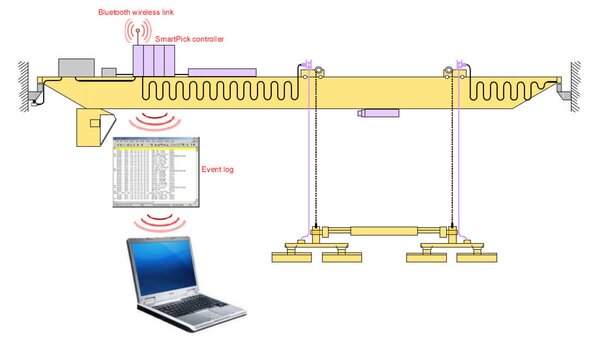
Figure 1: Accessing the event log using BlueTooth interface
The event log can be stored in a readable text file and e-mailed to a Truninger support centre for rapid analysis by a system specialist.
Inside the event log
All events logged have a unique event number and carry a date/time stamp; it is therefore possible to determine, to the nearest second, exactly when a particular event occurred. Events cover the following types of information:
- Magnet on/off cycles
- Magnet current and battery voltage
- Use of special features such as Partial Drop (order picking)
- Mains failures and battery switches
- Magnet lifting force selected during material handling operations
- Magnet and environment temperature
- State of crane interface signals
- System information: controller restarts, software versions, system id
- Changes to configuration data
Example: weak battery
The batteries play a critical role in the operational safety of a magnet system. Battery capacity is therefore tested every time the magnets are switched on and when insufficient, power on is aborted.
The following extract of the event log shows an attempt to switch on the magnets when battery test fails due to high voltage drop. Note that the most recent events appear first (so read bottom up for chronological order):
Event: 3398: 214 14:29:48 05.10 RB:chrg enabled 00000
Event: 3397: 145 14:29:44 05.10 Hoist lock OFF 00001
Event: 3396: 147 14:29:44 05.10 Travel lock OFF 00001
** Event: 3395: 012 14:29:20 05.10 RB:Bat test fail 01999
Event: 3394: 206 14:29:20 05.10 RB:bat voltage 00101
Event: 3393: 144 14:29:18 05.10 Hoist lock ON 00001
Event: 3392: 146 14:29:18 05.10 Travel lock ON 00001
Event: 3391: 213 14:29:18 05.10 RB:chrg disabled 00000
Event: 3390: 128 14:29:18 05.10 CB:VG ON 01000
The key events we see here are the following:
- Operator gives command to switch on a magnet (event 3390)
- Measured battery voltage just before battery test is 101 Volts (event 3394)
- Battery test fails because of excessive battery voltage drop (event 3395 data ‘999’)
Remote helpline
Remote troubleshooting: quick and easy with cell phone link
In case of failure or error in your controller, you can use Bluetooth interface to establish a direct ’helpline’ link between your SmartPick and a server located at the Truninger support centre. Figure 1 below gives an overview of how the link is built up:

Figure 1: Architecture of the remote helpline link
The link is setup in two steps:
- You first establish a Bluetooth connection between your cell phone and the faulty SmartPick controller.
- SmartPick can then be triggered to connect to the Truninger server using your cell phone's access point.
Once the link is established, a service technician can ’log in’ to your system, analysis the problem and provide detailed information about the breakdown and appropriate corrective action.
Modular construction
Why modularity?
The electrical components of Truninger magnet systems are composed of a number of discrete, separately orderable modules. This multi-level modularity offers a number of benefits:
- It allows mass production of modules based on tried and tested technology
- All cabinets have the same dimensions regardless of function
- All board/component level spares are available from stock
- Many operational features are software configurable
- Ease of integration and maintenance
- Scalability: easy to add extra magnet groups if required
Electrical component hierarchy

Figure 1: Hierarchy of electrical components
Maximum/minimum configuration
Modular cabinet design means the controller can be adapted to suit a wide range of applications. Figure 2 below shows a maximum configuration with battery backup and eight magnet groups:

Figure 2: SmartPickTM maximum configuration
Only two cabinets are required for a minimum configuration supporting a single magnet with no battery backup (cf. Figure 3). This arrangement would be suitable for a scrap magnet application for example.

Figure 3: SmartPickTM minimum configuration
Redundant magnet system
1. What is redundancy?
Electrical controls are built using a whole bunch of sub-systems each having a certain potential of failure. To provide safety of the system in case of a single sub-system failure, safety relevant subsystems are duplicated, generally referred to be “redundant”. Two sub-systems work on the same task and also cross-check each other to make sure, both systems work fine. Two redundant systems do not add much to safety, if failure of one system is not detected. Therefore, redundancy, cross-check and safety relevance are core elements of safety class 3 design also referred to in international standardization document DIN-EN 954-1.
2. Standard redundant components
The concept of redundancy is a central feature built-in Truninger magnet controller SmartPickTM. All safety relevant sub-systems are duplicated according to the safety class 3 standard.
The following sub-systems are covered:
- Two power sources- mains and backup battery
Backup battery capacity is designed to maintain safe operation for at least 20 minutes in case of mains power failure. - Two current sensors—two associated cross-checked signal processing units
Failure of one sensor will be detected and triggers a switch over to battery operation and system lock (magnet can be switched OFF but no more ON). - Two power drives—AC/DC & DC/DC
One drive dedicated to mains power AC/DC and one drive dedicated to battery power DC/DC. Failure of power electronics in any drive such as IGBT transistors will cause the second drive to take over and also lock the magnet system. - Two controllers built in different hard and software
Any failure of the SmartPickTM main controller will hand over the control task to the slave controller SafePickTM. - Two low voltage power sources
Each of the two controllers is equipped with individual low voltage power sources. Such power sources are continuously cross-checked and both are battery backed.
Optional redundant electric circuits
Most often, the power lines from the controller to the magnet are considered safe and therefore not built redundant. However, in some harsh environments, cables and cable drums can not be considered safe.
If required, two independent electric power circuits for one single magnet can be realised. Two cables, two cable drums, two electric coils in the magnet and two power modules PowerPickTM form such independent electric power circuits. Even a short cut at any location of one circuit will not stop this system from operating.
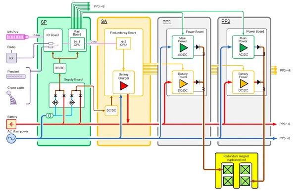
Figure 1: Redundant Magnet Controller SmartPickTM
| SP | Module SmartPick (SP), Nr. 1 CPU controlling AC/DC drive, signal inputs, redundant low power supply |
| SA | Modul SafePick (SA), Nr. 2 CPU controlling DC/DC drive, battery charger, battery supervision / maintenance (automatic capacity test) |
| PP 1 & 2 | Module PowerPick (PP), generates safe DC Power for magnet uniting mains- and battery power drive |
| InfoPick | Module InfoPick, graphic display informing the operator and staff on the ground visually and acoustically about the state of magnet system |
| Operation | Two operation units can be connected to SP, if one operation unit fails, the other unit can be used as backup |
| Magnet Coil | Redundant magnet with double coil each connected to one PP module, this results in safe power supply keeping up sufficient magnet force in case of any power circuit Coil failure |
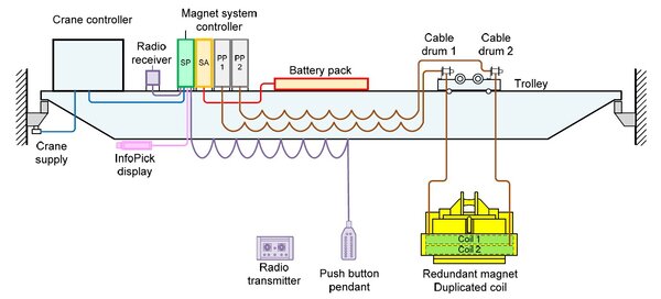
Figure 2: Magnet system on overhead crane
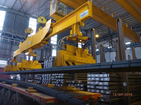
Figure 3: Redundant magnet system for bar bundles
Residual magnetism < 2mT
Why demagnetisation of the load
In material handling applications such as automated processing lines, residual magnetism can cause serious problems. The load may ‘stick’ to machine when traveling through the production line, small pieces of steel (washers, bolts, swarf, etc) may be attracted or welding arcs are displaced ‘blown’.
To avoid such effects, efficient demagnetisation of the load is essential. SmartPick offers configurable demagnetisation for eliminating a maximum amount of residual magnetism in minimum time.
What happens when steel becomes magnetised?
Ferromagnetic material such as steel which was never exposed to a magnetic field is made up of randomly ordered elementary magnets as represented below in Figure 1. Steel, when in this state, has no magnetic effect on its surroundings (see point a in Figure 3).

Figure 1: Elementary magnets in random order (material demagnetised)
When a magnetic field is applied, the elementary magnets start to align to such outer magnetic field. The stronger the magnetic field, the more the elementary magnets do get aligned. If all of the elementary magnets are aligned as shown in Figure 2:, the material is said to be magnetically saturated (Point b in Figure 3:). For steel magnetic saturation corresponds to about 2.4 Tesla.

Figure 2: All elementary magnets aligned (material magnetically saturated)
However, when the external magnetic field is removed, the elementary magnets do not return to their random state. This leaves some residual magnetism in the material, an effect known as remanence (Point c in Figure 3).
This residual magnetism has to be removed by some external means. The actual method applied depends mainly on the magnetic properties of the material. Material such as mild steel loses its magnetism quickly and is said to be ’soft magnetic’. Quality steel on the other hand, keeps its magnetism strongly and is therefore said to be ‘hard magnetic’.
RDS (Reverse Degauss System)
RDS demagnetisation eliminates residual magnetism from mild steel. Applying a magnetic field in the opposite direction causes the elementary magnets to gradually adopt a random alignment. When the opposing field is turned off (Point d in Figure 3:), the elementary magnets are randomly aligned, thus eliminating the residual magnetism.

Figure 3: Hysteresis of soft magnetic mild steel
RDS cannot be applied to hard magnetic material because the negative magnetic field causes all the elementary magnets to adopt a reverse alignment instead of returning to a random state.
DDS (Downcycle Degauss System)
DDS reduces the residual magnetism in hard quality steel by applying a series of polarity changes in a magnetic field of ever decreasing amplitude as shown below in Figure 4:

Figure 4: Typical magnet current behaviour during DDS demagnetisation
With this approach the elementary magnets are effectively ‘shaken’ into a random state, reducing the residual magnetism to around 2 mT.
Figure 5: shows the resulting hysteresis:

Figure 5: Hysteresis of hard magnetic quality steel