Security
Technologies for safe material handling
With TRUNINGER you are on the safe side.
Our technologies are designed to make material handling as safe as possible and avoid putting workers at risk.
Failure of our systems is virtually impossible because we rely on redundancy that keeps up power at all times. This minimizes risk of injury to your personnel while saving time and money along the way. Put your trust in TRUNINGER!
Main features of our safe lifting magnet solutions
- Total redundancy for maximum safety
- Redundant power feed from mains and backup battery
- SmartPick™ with parallel architecture (Safety class 3)
- Two synchronised power modules PowerPick™
- Double cable path from controller to magnet (including cable reelers)
- Magnet equipped with two redundant coils
Black Box / EventLog
A vital troubleshooting tool to minimise your system down time
Similar to the black box recorder of a modern aircraft, all major system events, faults and most operator actions are recorded in an event log. Up to 4,500 individual events can be stored in SmartPick’s non-volatile memory; this corresponds to approximately 200 load cycles of the magnet system.
In case of a breakdown, the events can be traced in detail making the event log a most valuable tool for troubleshooting . Detailed understanding of a problem allows to trigger the appropriate corrective action. Quite often, problems can be solved by telephone or email, saving a lot of time and cost as no specialist needs to rush on site. .
The event log can be accessed by laptop using SmartPickTM’s built-in BlueTooth module, nobody needs to climb up the crane (see figure 1 bellow).
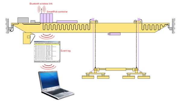
Figure 1: Accessing the event log using BlueTooth interface
The event log can be stored in a readable text file and e-mailed to a Truninger support centre for rapid analysis by a system specialist.
Inside the event log
All events logged have a unique event number and carry a date/time stamp; it is therefore possible to determine, to the nearest second, exactly when a particular event occurred. Events cover the following types of information:
- Magnet on/off cycles
- Magnet current and battery voltage
- Use of special features such as Partial Drop (order picking)
- Mains failures and battery switches
- Magnet lifting force selected during material handling operations
- Magnet and environment temperature
- State of crane interface signals
- System information: controller restarts, software versions, system id
- Changes to configuration data
Example: weak battery
The batteries play a critical role in the operational safety of a magnet system. Battery capacity is therefore tested every time the magnets are switched on and when insufficient, power on is aborted.
The following extract of the event log shows an attempt to switch on the magnets when battery test fails due to high voltage drop. Note that the most recent events appear first (so read bottom up for chronological order):
Event: 3398: 214 14:29:48 05.10 RB:chrg enabled 00000
Event: 3397: 145 14:29:44 05.10 Hoist lock OFF 00001
Event: 3396: 147 14:29:44 05.10 Travel lock OFF 00001
** Event: 3395: 012 14:29:20 05.10 RB:Bat test fail 01999
Event: 3394: 206 14:29:20 05.10 RB:bat voltage 00101
Event: 3393: 144 14:29:18 05.10 Hoist lock ON 00001
Event: 3392: 146 14:29:18 05.10 Travel lock ON 00001
Event: 3391: 213 14:29:18 05.10 RB:chrg disabled 00000
Event: 3390: 128 14:29:18 05.10 CB:VG ON 01000
The key events we see here are the following:
- Operator gives command to switch on a magnet (event 3390)
- Measured battery voltage just before battery test is 101 Volts (event 3394)
- Battery test fails because of excessive battery voltage drop (event 3395 data ‘999’)
Redundant magnet system
1. What is redundancy?
Electrical controls are built using a whole bunch of sub-systems each having a certain potential of failure. To provide safety of the system in case of a single sub-system failure, safety relevant subsystems are built double, generally referred to be “redundant”. Two sub-systems work on the same task and also cross-check each other to make sure, both systems work fine. Two redundant systems do not add much to safety, if failure of one system is not detected. Therefore, redundancy, cross-check and safety relevance are core elements of safety class 3 design concept also referred to in international standardization document DIN-EN 954-1.
2. Standard redundant components
The concept of redundancy is a central feature built-in Truninger magnet controller SmartPickTM. All safety relevant sub-systems are duplicated according to the safety class 3 standard.
The following sub-systems are covered:
- Two power sources- mains and backup battery
Backup battery capacity is designed to maintain safe operation for at least 20 minutes in case of mains power failure. - Two current sensors—two associated cross-checked signal processing units
Failure of one sensor will be detected and triggers a switch over to battery operation and system lock (magnet can be switched OFF but no more ON). - Two power drives—AC/DC & DC/DC
One drive dedicated to mains power AC/DC and one drive dedicated to battery power DC/DC. Failure of power electronics in any drive such as IGBT transistors will cause the second drive to take over and also lock the magnet system. - Two controllers built in different hard and software
Any failure of the SmartPickTM main controller will hand over the control task to the slave controller SafePickTM. - Two low voltage power sources
Each of the two controllers is equipped with individual low voltage power sources. Such power sources are continuously cross-checked and both are battery backed.
Optional redundant electric circuits
Most often, the power lines from the controller to the magnet are considered safe and therefore not built redundant. However, in some harsh environments, cables and cable drums can not be considered safe.
If required, two independent electric power circuits for one single magnet can be realised. Two cables, two cable drums, two electric coils in the magnet and two power modules PowerPickTM build up such independent electric power circuits. Even a short cut at any location of one circuit will not stop this system from operating.
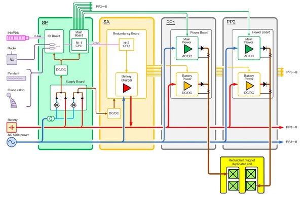
Figure 1: Redundant Magnet Controller SmartPickTM
| SP | Module SmartPick (SP), Nr. 1 CPU controlling AC/DC drive, signal inputs, redundant low power supply |
| SA | Module SafePick (SA), Nr. 2 CPU controlling DC/DC drive, battery charger, battery supervision / maintenance (automatic capacity test) |
| PP 1 & 2 | Module PowerPick (PP), generates safe DC Power for magnet uniting mains- and battery power drive |
| InfoPick | Module InfoPick, graphic display informing the operator and staff on the ground visually and acoustically about the state of magnet system |
| Operation | Two operation units can be connected to SP, if one of operation unit fails, another unit can be used as backup |
| Magnet Coil | Redundant magnet with double coil each connected to one PP module, this results in safe power supply keeping up sufficient magnet force in case of any power circuit Coil failure |
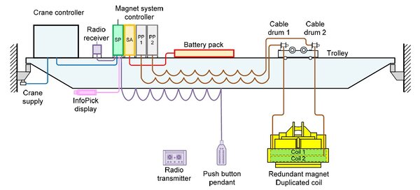
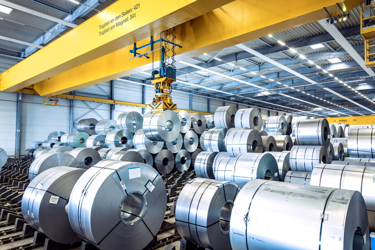
Figure 2: Magnet system on overhead crane
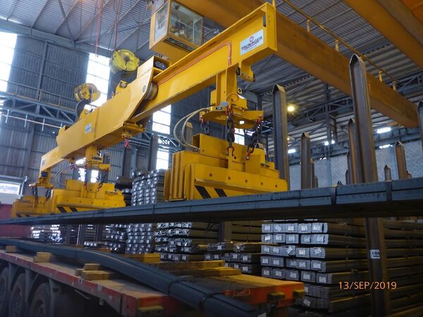
Figure 3: Redundant magnet system for bar bundles
Redundant architecture
Standardized, redundant components
The concept of redundancy is a central function of all electrical subsystems of TRUNINGER lifting magnet systems.
The first level of redundancy covers the failure of the mains supply and/or the failure of the main processor module. Most magnet systems are therefore equipped with the following components:
- SafePickTM module:
automatically switches to backup battery operation in the event of a mains power failure and also allows the magnets to be switched off when SmartPickTM main controller fails. - Backup battery:
Ensures power supply to the magnets for at least 20 minutes.
Option: Total redundancy
If required or desired, we build magnet systems with total redundancy. Further subsystems are also built redundant. Figure 1 shows such magnet system with total redundancy.

Figure 1: Magnet system with total redundancy
Two independent power circuits all the way from SmartPickTM down to the magnet coils.
Redundant components are:
- Two PowerPickTM modules.
- Two sets of flat cables.
- Two cable reelers.
- Two independent coils inside the magnet.
This arrangement guarantees safety of the load even in the event of partial or complete failure of one circuit.
A redundant man-machine interface ensures that the magnets may be operated also when radio receiver is faulty.